


Welding spatter occurs when small droplets of molten metal are expelled from the welding arc and land on surrounding surfaces. Although some spatter is normal during certain welding processes, excessive amounts can indicate problems with equipment settings, material conditions, or welding technique.
Spatter creates additional cleanup work and may affect the appearance of finished components. Metal droplets can adhere to nearby surfaces, interfere with subsequent finishing operations, and increase the time required to prepare welded assemblies.
Gas metal arc welding (GMAW), commonly called MIG welding, is particularly sensitive to the relationship between voltage, wire feed speed, shielding gas, and electrode extension. Understanding these factors helps welders identify the source of excessive spatter and make controlled adjustments.
Understand why welding spatter occurs
Welding spatter develops when molten metal transfers unevenly between the electrode and the weld pool.
During MIG welding, the wire electrode melts continuously as it feeds through the welding gun. Electrical energy creates an arc that transfers metal into the joint.
The transfer process influences how much spatter forms.
Short-circuit transfer involves repeated contact between the electrode and weld pool. Each short circuit can produce small metal droplets, especially when the welding parameters are poorly balanced.
Other transfer modes may produce less spatter under suitable operating conditions.
Excessive spatter should therefore be evaluated in relation to the welding process rather than treated as a separate problem.
Check the relationship between voltage and wire feed speed
Incorrect voltage and wire feed speed settings are common contributors to excessive welding spatter.
Voltage influences arc length and stability. Wire feed speed affects electrode delivery and, in many constant-voltage MIG systems, welding current.
When voltage is too low relative to wire feed speed, the electrode may repeatedly contact the weld pool in an unstable manner.
Excessive voltage can also create an unstable arc under certain operating conditions.
Lincoln Electric's welding troubleshooting guidance identifies voltage, wire feed speed, electrode extension, and travel technique as important variables when correcting spatter problems.
Welders should begin with the equipment manufacturer's recommended settings for the selected wire diameter, material thickness, shielding gas, and transfer mode.
Adjustments should be made gradually while observing arc behavior and weld appearance.
Consider the type and condition of the base metal
Different metals require different welding procedures and operating conditions.
Carbon steel, stainless steel, and aluminum have distinct thermal and electrical characteristics. These differences influence the welding process and the selection of compatible consumables.
For example, parameters appropriate for carbon steel should not automatically be applied to aluminum.
Surface conditions also influence arc behavior. Oil, dirt, moisture, and other contaminants can interfere with stable welding.
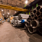
The material categories presented by Curtis Steel & Aluminum Co. include carbon steel, alloy steel, stainless steel, and aluminum, illustrating the range of metals commonly encountered in fabrication work.
Before welding begins, the base material should be identified and its surface condition evaluated.
Proper material identification helps establish the correct welding procedure and reduces unnecessary trial-and-error adjustments.
Maintain the correct electrode stickout
Electrode stickout refers to the length of welding wire extending beyond the contact tip.
Excessive stickout can affect electrical resistance, current, and arc stability.
When the wire extends too far, the welding process may become inconsistent, particularly if the operator cannot maintain a steady gun position.
Very short stickout can create other operating difficulties, including excessive heat near the contact tip.
The appropriate distance depends on the welding process, wire diameter, transfer mode, and equipment recommendations.
Welders should maintain a consistent electrode extension throughout the weld.
Sudden changes in gun distance can produce variations in arc behavior and increase spatter.
Evaluate shielding gas selection and flow
Shielding gas protects the molten weld pool from surrounding atmospheric contamination.
The gas composition can also influence arc characteristics and metal transfer.
Different shielding gas mixtures produce different results when welding carbon steel, stainless steel, or aluminum.
For example, carbon dioxide and argon-based mixtures can produce different arc characteristics during MIG welding.
Insufficient shielding gas flow may contribute to unstable welding conditions, while excessive flow can create turbulence that interferes with shielding effectiveness.
Gas hoses, regulators, and connections should be checked for leaks or restrictions.
Air movement from fans, open doors, or ventilation equipment may also disturb the shielding gas.
The correct gas type and flow rate should follow the approved welding procedure and equipment guidance.
Inspect welding wire and equipment condition
Contaminated welding wire can introduce additional problems into the welding process.
Wire exposed to moisture, oil, or excessive dirt may contribute to inconsistent feeding and unstable arc conditions.
The wire feeder should deliver material smoothly without slipping, binding, or sudden changes in speed.
Worn contact tips, damaged liners, and incorrectly adjusted drive rolls can interfere with consistent electrode movement.
Miller Electric identifies dirty wire, excessive electrode extension, incorrect polarity, and shielding gas problems among the possible causes of excessive spatter in its welding troubleshooting guidance.
The reference page outlining welding consumables, equipment, and safety products identifies welding machines, electrodes, consumables, gloves, and protective apparel associated with fabrication activities.
These product categories relate to different aspects of welding preparation, equipment operation, and worker protection.
Equipment condition should be checked before changing multiple welding parameters.
Adjust welding gun angle and travel speed
Welding technique affects how molten metal enters the weld pool.
An inconsistent gun angle may change arc direction and contribute to uneven metal transfer.
Travel speed also influences the amount of heat applied to a particular section of the joint.
Excessively fast movement may produce an irregular bead, while overly slow movement can introduce excessive heat or unwanted metal buildup.
The correct technique depends on the welding position, joint configuration, transfer mode, and material thickness.
A steady travel speed and consistent gun angle generally help maintain predictable welding conditions.
Operators should avoid abrupt changes in movement unless required by the welding procedure.
Practice welds on representative material can help identify suitable settings before production welding begins.
Verify electrical connections and polarity
Poor electrical connections can contribute to unstable welding performance.
Loose work lead connections, damaged cables, or unsuitable contact points may interfere with consistent current flow.
The work connection should be secure and attached to an appropriate location.
Polarity must also match the welding process and consumable requirements.
An incorrect polarity setting can significantly affect arc behavior and weld quality.
Before troubleshooting more complex problems, welders should confirm that the equipment is connected and configured according to the manufacturer's instructions.
Electrical inspections and repairs should be performed only by personnel qualified to carry out the relevant work safely.
Use a systematic troubleshooting process
Several welding variables can contribute to spatter simultaneously.
Changing voltage, wire feed speed, shielding gas, and travel technique at the same time makes it difficult to identify which adjustment improved the result.
A controlled troubleshooting process begins by confirming the welding procedure, material type, wire diameter, and equipment condition.
The operator can then examine arc stability, spatter distribution, and weld bead appearance.
One parameter should be adjusted at a time when the approved procedure permits changes.
Trial welds should be inspected before the revised settings are used on production components.
Reduced spatter alone does not confirm weld quality. Penetration, fusion, bead profile, and applicable inspection requirements must also be satisfied.
Consistent welding results depend on properly matched parameters, suitable consumables, clean materials, maintained equipment, and controlled technique.